Steam generation in boiler tubes is based on nucleate boiling. This means that a multiple of small steam bubbles are generated on the inside wall of the tube which remains "wet". If steam generation in any portion of the tube becomes excessive, film boiling results, which increases resistance to heat transfer and elevates the tube temperature. Steam blanketing can occur at low heat fluxes, in the region of nucleate boiling, if the steam bubbles formed are not continuously removed. At heat flues of 400,000 Btu/hr/ft2 and above, nucleate boiling changes to film boiling. At this point, even the most vigorous circulation cannot prevent the formation of an insulating steam film on the heating surface. To provide a reasonable factor of safety, HRSG's should be designed for a maximum heat flux of 100,000 Btu/hr/ft2.
The operating pressure of the evaporator also has a direct relation to the required circulation to achieve nucleate boiling. Since at a low pressure, the specific volume of the vapor is greater than at higher pressures, the circulation ratio must be greater at the lower pressure than at the higher. So, where a 10 :
ratio may be satisfactory for a system operating at 600 psia, you may need a 25 : 1 ratio for a 100 psia system.
For more specific information on circulation ratios and design of different configurations, see the Forced Circulation and Thermosyphon Circulation sections.
Forced Circulation
A forced circulation system uses a pump to maintain circulation in all the tubes of the evaporator tube bundle. A typical forced circulation system is shown at the right. The water is distributed within an inlet header to the various parallel circuits and the steam and water mixture is collected in an outlet header. The mixture is returned to a drum for separation of the steam and water.
The tubes may have any orientation but are generally horizontal with an upward water flow to improve stability between the parallel channels. The forced circulation evaporator will generally have more flow resistance than a natural circulation evaporator. In low pressure drop tube bundles, inlet orifices may be required to provide for better distribution to the parallel circuits.
When designing the circultion rate for these HRSG's these factors must be weighed agaist the cost of the pump and the pumping energy. Experience in steam boilers has shown that the "danger" zone in which film boiling can be expected to occur is between 20 and 25 percent steam generation by weight. This has led to the rule of thumb for a 5 : 1 circulation ratio. Unfortunately, this is in fact borderline and does not allow sufficient conservatism for unusual or extreme cases. For instance, an HRSG with a very long horizontal tube length(some units hav been manufactured with tubes as long as a hundred feet).
Also, the relation of the drum to the evaporator coil needs to be considered. As an example a steam coil in a fired heater may have the steam separation drum located a hundred feet away and at the geround, where the coil may be fifty feet up on top of the heater. In this case, the water pressure in the evaporator may be such that instead of total vaporization occuring in the coil, the temperature rises instead, and the major vaporization occurs at the inlet separators in the steam drum. In these cases, a 3 : 1 circulation ratio may be sufficient.
Thermosyphon(Natural) Circulation
Conventional, vertical tube boilers are generally designed for natural, "thermosyphon", circulation. This means the water and steam/water circuits are arranged so that the two phase mixture in the steam generating tubes rises to the steam drum by thermal lift of differential density and is replaced by water from the drum by gravity flow. However, it should be noted that many horizontal tube natural circulation boilers have been sucessfully used for years.
Although the nature of a thermosyphon circulation boiler is quite simple, the calculation procedure to check the design to see what the circulation ratio is, can become very complicated. Most designs are such that each row of tubes have a different circulation than all the other rows, but some actually have a different circultion ratio for every tube in the evaporator, which would be difficult to determine, and probably not worth while. That is, of course, that an over all conservative check can be made that is reliable.
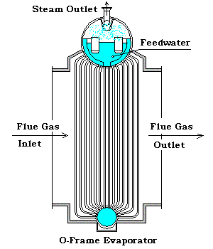
To take a look at the details of a thermo syphon evaporator, we will use the ever popular O-Frame design.
We will assume that our evaporator has the following design :
Mechanical :
SA178 Gr. A, 2.0" OD tubes with 0.120" wall, 28'-0" effective length, 28 tubes per row.
12 rows of finned tubes with 0.049" thick x 0.75" high x 6 fins per in.
2 bare downcomer rows located in the middle of the 12 finned rows.
All tubes set on a triangular pitch.
48" ID steam drum and 24" ID mud drum located 33'-0" centerline to centerline.
Process Conditions :
Gas Side : 800,000 lbs/hr of Gas Turbine Exhaust at 898 °F
Gas Properties : Volume %
Nitrogen, N2
72.55
Oxygen, O2
12.34
Carbon Dioxide, CO2
3.72
Water, H2O
10.52
Argon, Ar
0.87
Sulphur Dioxide, SO2
0.0
Carbon Monoxide, CO
0.0
Tube Side : Steam is saturated at 630 psia.
So what we want to do first is select a single circuit in the system to review. We can do that with the sketch shown to the right. The 28 riser tubes would all be the same on this row. The 28 downcomer tubes would likewise be the same. The downcomers , both rows, 56 tubes, feed all the 336 of the riser tubes, so the circuit cannot be isolated from the rest of the circuits. If the heat absorbed by the downcomer tubes is so little that it will not cause a significant difference in the water density of that column, then we will be able to ignore the heat absorbed, for the purposes of checking the circulation. If this is true, then we would have one loss from the drum water down and through the mud drum up to the start of the heating zone of the riser. Another loss could be associated with the heating zone and a third loss covering from the end of the heating zone, up and through the primary separator.
The next step will be to determine the flux rate for each row of tubes through the unit so we can first see if the downcomer is going to be a significant heating tube. Also, we will need the flux rate on a row by row bases to determine the individual tube steam generation.
Row No.
Flux Rate, Btu/hr/ft2
Tube Surf., ft2
Vapor Flow, lbs/hr
1
3,232
176.9
788
2
2,619
176.9
639
3
2,127
176.9
519
4
1,730
176.9
422
5
1,411
176.9
344
6
1,152
176.9
281
7
1,781
14.7
N/A
8
1,730
14.7
N/A
9
889
176.9
217
10
728
176.9
178
11
597
176.9
146
12
490
176.9
120
13
403
176.9
98
14
331
176.9
81
The total absorbed duty for the evaporator is 79,268,244 Btu/hr, or 109,288 lbs/hr of steam generated. If we assume, for now, that the circulation ratio is 10:1, then the water flow through the downcomer tubes will be about 1,092,880 lbs/hr, or 19,516 lbs/hr/tube. The pressure losses in the downcomers are, the sudden entry loss, the friction loss, and the sudden exit loss. This results in a pressure loss of 0.225 + 0.927 + 0.113 = 1.265 psi. But, since the head of water in the system is 11.322 psi, no vaporization will occur in the downcomers because the water in the mud drum is well above saturation for the system. The head of water/vapor in the riser leg will be less than that in the downcomer which will cause the water to circulate, thus, a thermosyphon system. How much circulation is what we need to determine.
We can break down the downcomer portion of the circuit as follows:
Sudden entry into downcomer tube :
0.5 velocity heads
Friction loss in downcomer tube :
friction loss for 30'-0" of tube
Sudden exit into mud drum :
1.0 velocity heads
These losses are the same for all 56 downcomer tubes.
For the riser tube, up to the start of the heating zone:
Sudden entry into riser tube :
0.5 velocity heads
Friction loss in riser tube :
friction loss for varing lengths of tube
Bend loss in riser tube :
bend loss for varing angle of bend
These losses would be the same for each tube in a row, but different between each row.
For the riser tube heating zone:
Friction loss in riser tube :
friction loss for 28'-0" of tube
These losses would be the same for each tube in a row, but different between each row.
For the riser tube, from end of the heating zone to steam drum:
Friction loss in riser tube :
friction loss for varing lengths of tube
Bend loss in riser tube :
bend loss for varing angle of bend
Sudden exit into steam drum baffle :
1.0 velocity heads
Primary separator loss :
See Centrifugal Pressure Drop below
These losses would be the same for each tube in a row, but different between each row.
As you can see, we have a major problem in calculating the pressure loss for the primary separators since we do not have an actual design. So we will establish a proceedure to estimate the number of centrifugal separators that we need for this sample. Then we will establish a formula for the pressure loss if we know the number of centrifugals.
Of course, if you are checking an existing design, you would know the number of centrifugal separators it has. It should also be noted that many steam drums don't use centrifugal separators, but rather a system of baffles, especially in low pressure systems.
If you are wondering why we didn't just say up front that, normally, these separators are sized at approximately 1.0 psi drop at design load, the answer is, we needed to get these complicated looking formulas established for our circulation calculations.
The method we have outlined above will give us a conservative answer since we will assume vaporization begins at the start of the heating zone, where it actually starts up the tube aways, and the final vaporization doesn't occur until separation in the centrifugals since it is only here that it is fully back to saturation temperature and pressure.
Since the flux rate on the first row of tubes is greatest, it will have the least circulation ratio, and the last row, where the flux is the least, will have the greatest circulation ratio. With our assumtion of a 10:1 circulation ratio, we will determine what the available loss for the rest of the circuit is,
Head in downcomer = rl * hhead= 49.407 * 33 = 1630.43 lb/ft2 * 1/144 = 11.322 psi
Head in riser up to heating zone = rl * hhead = 49.407 * 2 / 144 = 0.686 psi
Head in riser heating zone = rm * hhead = 1/{[(0.02024 * 9.5) + (0.73206 * 0.5)]/10} * 28 / 144 = 3.483 psi
Head in riser from heating zone = rm * hhead = 1/{[(0.02024 * 9.0) + (0.73206 * 1.0)]/10} * 3 / 144 = 0.228 psi
Head in riser total = 0.686 + 3.483 + 0.228 = 4.397 psi
Left for riser losses = 11.322 - 4.397 - Dpdc= 11.322 - 4.397 - 1.265 = 5.660 psi
The problem with trying to analyze the circulation as we are here, is that the riser circulation is not 10:1, it is actually different for each of the 12 different sets of risers, and the downcomer data is not corrected for the combination of the 12 risers sets feeding the 2 downcomer sets. It is easy to see then, that any analysis must compute all 12 riser sets and the 2 downcomer sets at the same time, or the analysis is incorrect.
Having said this, we will now set up a JavaScript which will balance one riser set against one downcomer set, to provide us with practice in balancing these circuits.
You will notice that when we run the whole evaporator as a single unit, we get a circulation ratio of 18.31:1, which we know from above is not correct. But, we can use our calculator and perform other checks as we would do if we were checking the circulation by hand. If you change the number of riser rows to 1, the lower straight length to 3', the upper to 2', the angle of the upper turn to 45 °, and the lower to 90°. Now for the downcomers, if we divide the number of downcomers by the number of riser rows, we get 6 downcomers to feed each row of risers. So change the downcomers to 1 row with 6 tubes wide. Then change the flux to the first row flux, 3,232 Btu/hr-ft2
We now calculate 10.58:1 circulation ratio for first row. Now change the flux rate to the last row, 331 Btu/hr-ft2 and we get a rate of 56.93:1. These checks, at least give us an approximation of the actual circulations that we would get with a program that can balance all the rows at the same time.
Sizing the riser circuits
The risers which we will be dicussing on this page are those that are generally external to the heat transfer sections. Since when the riser and the heat transfer are the same, the selection and sizing are based on the heat transfer requirement, i.e., the steam rate, and the circulation design. The circulation for the HRSG is discussed in previous pages.
The risers which we are now concerned with would be those found on I-Frame evaporators, horizontal tube evaporators, etc. This type riser is normally constructed of standard pipe and is connected to a header at the evaporator outlet with the other end connected to the steam drum.
Minimum riser flow area should be based on the following:
The target velocity in an individual riser pipe should be less than 12 ft/sec. The minimum number of riser pipes per header should be two. If the header is more than six feet and less than twelve feet in length, the preferred number of risers is three. For longer lengths, a similar number should be provided to prevent distribution problems in the header or manifold.
Sizing the downcomer circuits
The downcomers which we will be dicussing on this page are those that are generally external to the heat transfer sections. The circulation for the HRSG is discussed in previous pages.
The downcomers which we are now concerned with would be those found on I-Frame evaporators, horizontal tube evaporators, O-Frame, A-Frame and D-Frame evaporators with external downcomers. This type downcomer is normally constructed of standard pipe and is connected to upper drum with the other end connected to the lower drum or header.
Minimum downcomer flow area should be based on the following:
Amin = 0.007996 * Wg * Voll * CR
Where,
Amin
=
Downcomer area, in
Wg
=
Gross water flow, lb/hr
Voll
=
Liquid specific volume, ft3
A
=
Circulation ratio of evaporator coil
The target velocity in an individual downcomer pipe should be less than 6 ft/sec. The minimum number of downcomer pipes per header is one. If the header is more than six feet and less than twelve feet in length, the preferred number of downcomers is two. For longer lengths, a similar number should be provided to prevent distribution problems in the header or manifold.