| Home | | | Scope | | | Types/Configs. | | | Schematics | | | Heat Balance | | | Heat Trans1 | | | Heat Trans2 | | | Process | | | Circulation | | | Other | | | Publications | | | Calculators |
The properties of water and steam have been described by the “International Association for the Properties of Water and Steam”. The latest release is the IAPWS97 document, which is available at this site under publications. This document includes formulas for the various properties which make it fairly simple to develop software for use in HRSG design and rating. The formulation suggested for industrial use is the IAPWS-IF97 which replaces the 1967 document, IFC67. It should be noted that there is no significant differences in these two sets of formulations, in the pressure and temperature ranges normally used in HRSGs. The following JavaScript calculator is based on the IFC67 formulations. This calculator has not been tested throughout the overall range of pressure and temperatures covered by these formulations, but should be sufficient for the purposes of this introduction to HRSG design.
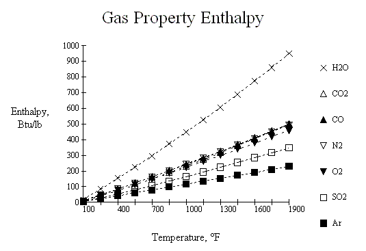
The thermal properties for flue gas used in these procedures are curve fits of the following families of curves. The source for these curves is not currently known, as they were originally constructed some thirty years ago as we were developing some of the software proceedures presented herein. However, the reliability of these values seem to be very suitable for HRSG design.

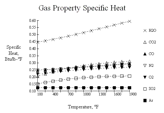
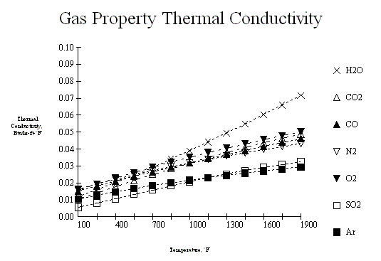
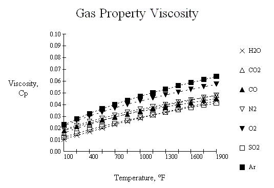
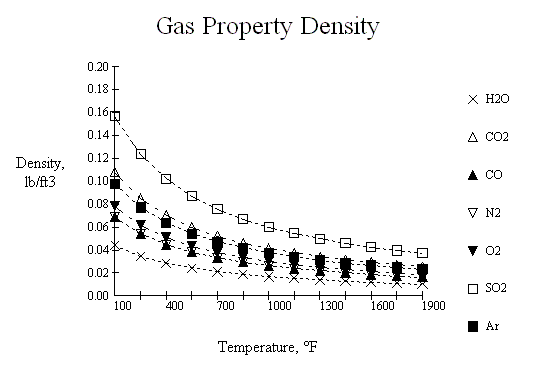
Below is a JavaScript calculator which can interpret these curves.
The supplemental combustion in HRSG systems takes place in a burner which usually is located in the flue gas stream going to the HRSG. However, some systems because of high firing requirements and low O2 in the flue gas, may require to be fired externally to the flue gas stream and may reuire additional combustion air. The types of burners and how they function are not covered in detail in this section. The amount of heat released can be easily calculated for a gas when we know the composition of the fuel and the heating values of the various components. For liquid fuels, the heating values are obtained by a calorimeter test.
From these values and using the standard combustion equation, we can determine the composition of the flue gas leaving the burner. As an example, the combustion of methane could be stated :
The following Lower Heating Values(LHV) are used in this script:
| Component | Btu/lb | Component | Btu/lb | Component | Btu/lb |
| CH4 | 21,520 | C2H6 | 20,432 | C3H8 | 19,944 |
| N-C4H10 | 19,680 | I-C4H10 | 19,629 | N-C5H12 | 19,517 |
| I-C5H12 | 19,478 | C6H14 | 19,403 | CO | 4,347 |
| H2 | 51,623 | N2 | 0 | CO2 | 0 |
| C | 14,093 | S | 3,983 | C2H4 | 20,295 |
| C3H6 | 19,691 | C4H8 | 19,496 | C6H6 | 17,480 |
| H2O | 0 | O2 | 0 | H2S | 6,545 |
The inside film coefficient needed for the thermal calculations may be estimated by several different methods. The API RP530, Appendix C provides the following methods,
For liquid flow with Re =>10,000,| hl = Heat transfer coefficient, liquid phase, Btu/hr-ft2-°F |
| k = Thermal conductivity, Btu/hr-ft-°F |
| di = Inside diameter of tube, ft |
| mb = Absolute viscosity at bulk temperature, lb/ft-hr |
| mw = Absolute viscosity at wall temperature, lb/ft-hr |
| hv = Heat transfer coefficient, vapor phase, Btu/hr-ft2-°F |
| Tb = Bulk temperature of vapor, °R |
| Tw = Wall Temperature of vapor, °R |
| G = Mass flow of fluid, lb/hr-ft2 |
| Cp = Heat capacity of fluid at bulk temperature, Btu/lb-°F |
| htp = Heat transfer coefficient, two-phase, Btu/hr-ft2-°F |
| Wl = Weight fraction of liquid |
| Wv = Weight fraction of vapor |
The intube pressure drop may be calculated by any number of methods available today, but the following procedures should give sufficient results for HRSG design. The pressure loss in HRSG tubes and fittings is normally calculated by first converting the fittings to an equivalent length of pipe. Then the average properties for a segment of piping and fittings can be used to calculate a pressure drop per foot to apply to the overall equivalent length. This pressure drop per foot value can be improved by correcting it for inlet and outlet specific volumes.
Friction Loss:| Dp = Pressure drop, psi |
| di = Inside diameter of tube, in |
| G = Mass velocity of fluid, lb/sec-ft2 |
| Vlm = Log mean specific volume correction |
| F = Fanning friction factor |
| Lequiv = Equivalent length of pipe run, ft |
| V1 = Specific volume at start of run, ft3/lb |
| V2 = Specific volume at end of run, ft3/lb |
| Vi = Specific volume at point, ft3/lb |
| Tf = Fluid temperature, °R |
| Pv = Press. of fluid at point, psia |
| MWv = Molecular weight of vapor |
| Vfrac = Weight fraction of vapor %/100 |
| rl = Density of liquid, lb/ft3 |
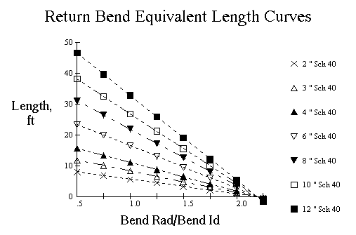
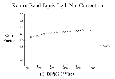
The equivalent length of a return bend may be obtained from the following curves based on Maxwell table and can be corrected using the Reynolds number correction factor.
| FactNre = Reynolds number correction |
| Lrb = Equivalent length of return bend, ft |
| G = Mass velocity, lb/sec-ft2 |
| Di = Inside tube diameter, in |
| Visc = Viscosity, cp |
Now that we have all the details described, we can calculate the pressure drop for some typical heater coils.