| Afghan Energy, Chemical & Mining Industries resource for Renewable Energies, Irrigation & Sustainable Industries. |
Ammonia ProductionIn 1909 Fritz Haber established the conditions under which nitrogen, N2(g), and hydrogen, H2(g), would combine using
This process produces an ammonia, NH3(g), yield of approximately 10-20%. The Haber synthesis was developed into an industrial process by Carl Bosch. The reaction between nitrogen gas and hydrogen gas to produce ammonia gas is exothermic, releasing 92.4kJ/mol of energy at 298K (25oC).
By Le Chetalier's Principle:
Rate considerations:
Uses of Ammonia
A Brief HistoryAt the beginning of the 20th century there was a shortage of naturally occurring, nitrogen-rich fertilisers, such as Chile saltpetre, which prompted the German Chemist Fritz Haber, and others, to look for ways of combining the nitrogen in the air with hydrogen to form ammonia, which is a convenient starting point in the manufacture of fertilisers.This process was also of interest to the German chemical industry as Germany was preparing for World War I and nitrogen compounds were needed for explosives. The hydrogen for the ammonia synthesis was made by the water-gas process (a Carl Bosch invention) which involves blowing steam through a bed of red hot coke resulting in the separation of hydrogen from oxygen. The nitrogen was obtained by distillation of liquid air, then by cooling and compressing air. These days, the hydrogen is produced by reforming light petroleum fractions
or natural gas (methane, CH4) by adding steam:
Enough steam is used to react with about 45% of the methane (CH4), the rest of the methane is reacted with air:
All the carbon monoxide (CO) in the mixture is oxidised to CO2 using steam and an iron oxide catalyst:
The carbon dioxide (CO2)is removed using a suitable base so that only the nitrogen gas (N2)and hydrogen gas (H2)remain and are used in the production of ammonia (NH3). In ammonia production the hydrogen and nitrogen are mixed together in a ratio of 3:1 by volume and compressed to around 200 times atmospheric pressure. ProductionFeedstock:The original feedstock for the old 1,000-ton-per day Allied Chemical ammonia plant at Hopewell, VA, USA, was water gas (i.e., illuminating gas), the same type of gas that was manufactured for heating, lighting and cooking in cities before natural gas became available. It was made from coke and steam. Allied/Hopewell made enough such gas per day to have supplied a city the size of New York Feedstocks may range from, ethane through petroleum naphtha to petroleum gas oils. The basic processing scheme used for such feedstocks is the same as for a natural gas feedstock, however ammonia eventually is made by mixing hydrogen with nitrogen. It requires a catalytic conversion reactor followed by cooling the hot reactor effluent gas: first by generating steam with the hot effluent gas and then by using mechanical refrigeration to separate out the liquified anhydrous ammonia. It also requires compressing the catalytic reactor feed gases to a range of 100 to 250 bar, depending on the reactor process being used. Here is the ammonia process with Gas feedstock which is a guideline to the original and most used process. 2. DESCRIPTION OF PRODUCTION PROCESSES 2.1 Production Processes in Operation in Europe Two main types of production process for ammonia synthesis gas are currently in operation in Europe:- - Steam reforming of natural gas or
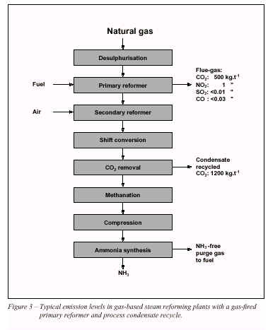
other light hydrocarbons (Natural Gas Liquids, In at least one partial oxidation unit, natural gas is used as feedstock. Coal gasification and water electrolysis are no longer in use in the European ammonia industry. The ammonia synthesis process is principally independent of the type of synthesis gas pro-duction process, but synthesis gas quality influences the loop design and operating conditions. A block diagram of the conventional steam reforming process is shown in Figure 1. (In some cases, a separate auxiliary boiler is required). About 85% of world ammonia production is based on steam reforming concepts [3]. A process description is given in 2.2.1.
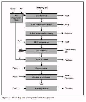
For heavier feedstocks than naphtha, partial oxidation with oxygen is used in the synthesis gas production. A block diagram of a typical partial oxidation process is shown in Figure 2, and a process description is given in 2.2.5. 2.2 BAT Production Processes No single process can be identified as BAT for the production of ammonia. In this chapter the characteristics of BAT processes based on available feedstocks are described. Other BAT processes may also exist. Natural gas reforming with steam and air is the simplest and most efficient way of ammonia synthesis gas production. Comparing natural gas reforming, heavy oil and coal gasification gives the following approximate relative consumption figures, based on modern technological standards for each route, at European economic conditions:-
Based on the known resources of fossil raw materials, it is likely that natural gas will domi-nate as the feedstock for ammonia for the next 50 years at least. In the very long term, 50-200 years, one might expect coal to take over, based on world reserves and consumption rate. Heavy oil may be attractive under special environmental concerns, when natural gas is not available and the partial oxidation process could solve a waste problem (heavy residues, plastics recycle). For the present time and the near future, the steam/air reforming concepts based on natural gas and other light hydrocarbons are considered to be the dominating group of BAT production processes. The BAT reforming processes can be divided into the following types:- - Conventional steam reforming with
a fired primary reformer and stoichiometric air secondary reforming
(stoichiometric H/N-ratio) For heavy feedstocks, partial oxidation is considered as the BAT production process. All three reforming versions, and partial oxidation of heavy residues, are operated in Europe today. The following description concentrates on presenting the conventional steam reforming process and only deviations and additions will be described for the other BAT processes. 2.2.1 Conventional steam reforming 2.2.1.1 Overall conversion The theoretical process conversions, based on methane feedstock, are given in the following approximate formulae:-
0.88CH4 + 1.26Air +
1.24H2O -----> 0.88CO2 + N2 + 3H2 The synthesis gas production and purification normally take place at 25-35bar pressure. The ammonia synthesis pressure is usually in the range 100-250bar. For more detailed process flow sheets refer to Ullmann [3]. 2.2.1.2 Feedstock desulphurisation Most of the catalysts used in the process are
sensitive to sulphur and sulphur compounds. The feedstock normally contains up
to 5mg S.Nm-3 as sulphur compounds. The feed-gas is pre-heated to
350-400 �C, usually in the primary reformer convection section, and then treated
in a desulphurisation vessel, where the sulphur compounds are hydrogenated to
H2S, typically using a cobalt molybdenum catalyst, and then adsorbed
on
R-SH + H2 -----> H2 S
+ RH In this way, the sulphur is removed to less than 0.1ppm S in the gas feed. The zinc sulphide remains in the adsorption bed. The hydrogen for the reaction is usually recycled from the synthesis section. 2.2.1.3 Primary reforming The gas from the desulphuriser is mixed with process steam, usually coming from an extraction turbine, and the steam/gas mixture is then heated further to 500-600 �C in the convection section before entering the primary reformer. In some new or revamped plants the preheated steam/gas mixture is passed through an adiabatic pre-reformer and reheated in the convection section, before entering the primary reformer. (Special pre-reformer catalysts are offered by several suppliers). Also, in some plants, part of the process steam is supplied by feed-gas saturation. The amount of process steam is given by the process steam to carbon molar ratio (S/C-ratio), which should be around 3.0 for the BAT reforming processes. The optimum ratio depends on several factors, such as feedstock quality, purge gas recovery, primary reformer capacity, shift operation, and the plant steam balance. In new plants the optimum S/C-ratio may be lower than 3.0. The primary reformer consists of a large number of high-nickel chromium alloy tubes filled with nickel-containing reforming catalyst. The overall reaction is highly endothermic and additional heat is required to raise the temperature to 780-830 �C at the reformer outlet. The composition of the gas leaving the primary reformer is given by close approach to the following chemical equilibria:-
CH4 + H20 <--->
CO + 3H2 C0 + H20 <--->
CO2 + H2 The heat for the primary reforming process is supplied by burning natural gas or other gaseous fuel, in the burners of a radiant box containing the tubes. The flue-gas leaving the radiant box has temperatures in excess of 900 �C, after supplying the necessary high level heat to the reforming process. Thus only about 50-60% of the fuel’s heat value is directly used in the process itself. The heat content (waste heat) of the flue-gas is used in the reformer convection section, for various process and steam system duties. The fuel energy requirement in the conventional reforming process is 40-50% of the process feed-gas energy. The flue-gas leaving the convection section at 100-200 �C is one of the main sources of emissions from the plant. These emissions are mainly CO2, NOx, with small amounts of SO2and CO. 2.2.1.4 Secondary reforming Only 30-40% of the hydrocarbon feed is reformed in the primary reformer because of the chemical equilibria at the actual operating conditions. The temperature must be raised to increase the conversion. This is done in the secondary reformer by internal combustion of part of the gas with the process air, which also provides the nitrogen for the final synthesis gas. In the conventional reforming process the degree of primary reforming is adjusted so that the air supplied to the secondary reformer meets both the heat balance and the stoichiometric synthesis gas requirement. The process air is compressed to the reforming pressure and heated further in the primary reformer convection section to around 600 �C. The process gas is mixed with the air in a burner and then passed over a nickel-containing secondary reformer catalyst. The reformer outlet temperature is around 1,000 �C, and up to 99% of the hydrocarbon feed (to the primary reformer) is converted, giving a residual methane content of 0.2-0.3% (dry gas base) in the process gas leaving the secondary reformer. The process gas is cooled to 350-400 �C in a waste heat steam boiler or boiler/superheater downstream from the secondary reformer. 2.2.1.5 Shift conversion The process gas from the secondary reformer contains 12-15% CO(dry gas base) and most of the COis converted in the shift section according to the reaction:-
CO + H2O <--->
CO2 + H2
In the High Temperature Shift (HTS) conversion, the gas is passed through a bed of iron oxide/chromium oxide catalyst at around 400 �C, where the COcontent is reduced to about 3% (dry gas base), limited by the shift equilibrium at the actual operating temperature. There is a tendency to use copper containing catalyst for increased conversion. The gas from the HTS is cooled and passed through the Low Temperature Shift (LTS) converter. This LTS converter is filled with a copper oxide/zinc oxide-based catalyst and operates at about 200-220 �C. The residual COcontent in the converted gas is about 0.2-0.4% (dry gas base). A low residual CO content is important for the efficiency of the process. 2.2.1.6 CO2 removal The process gas from the low temperature shift converter contains mainly H2, N2, CO2and the excess process steam. The gas is cooled and most of the excess steam is condensed before it enters the CO2removal system. This condensate normally contains 1,500-2,000ppm of ammonia800-1,200ppm of methanol. Minor amounts of amines, formic acidand acetic acidcould be present in the condensate. All these components should be stripped from the condensate and/or recycled in BAT processes. The heat released during cooling/condensation is used for:- -The regeneration of the
CO2scrubbing
solution The amount of heat released depends on the process steam to carbon ratio. If all this low-level heat is used for CO2removal or absorption refrigeration, high-level heat has to be used for the feedwater system. An energy-efficient process should therefore have a CO2removal system with a low heat demand. The CO2is removed in a chemical or a physical absorption process. The solvents used in chemical absorption processes are mainly aqueous amine solutions ( Mono Ethanolamine (MEA), Activated Methyl DiEthanolamine (aMDEA)or hot potassium carbonatesolutions. Physical solvents are glycol dimethylethers (Selexol), propylene carbonate and others. The MEA process has a high regeneration energy consumption and is not regarded as a BAT process. For new ammonia plants the following CO 2 removal processes are currently regarded as BAT:- - aMDEA standard 2-stage process, or similar Concepts such as Pressure Swing Adsorption (PSA) should also be regarded as BAT in some new plants but in such cases CO2removal is not the only function of the PSA unit. The typical range of heat consumption in the modern chemical absorption process is 30-60MJ.kmol -1 CO2. The physical absorption processes may be designed for zero heat consumption, but for comparison with the chemical processes, the mechanical energy requirements have also to be considered. Residual CO2contents are usually in the range 100-1,000ppmv, dependent on the type and design of the removal unit. Contents down to about 50ppmv are achievable. 2.2.1.7 Methanation The small amounts of CO and CO2, remaining in the synthesis gas, are poisonous for the ammonia synthesis catalyst and must be removed by conversion to CH4 in the methanator:- CO + 3H2 -----> CH4 + H2O CO2+ 4H2 -----> CH4 + 2H2O The reactions take place at around 300 �C in a reactor filled with a nickel containing cata-lyst. Methane is an inert gas in the synthesis reaction, but the water must be removed before entering the converter. This is done firstly by cooling and condensation downstream of the methanator and finally by condensation/absorption in the product ammonia in the loop or in a make-up gas drying unit. 2.2.1.8 Synthesis gas compression and ammonia synthesis Modern ammonia plants use centrifugal compressors for synthesis gas compression, usually driven by steam turbines, with the steam being produced in the ammonia plant. The refrigeration compressor, needed for condensation of product ammonia, is also usually driven by a steam turbine. The synthesis of ammonia takes place on an iron catalyst at pressures usually in the range 100-250bar and temperatures in the range 350-550 �C:-
N2 + 3H2 <--->
2NH3
Only 20-30% is reacted per pass in the converter due to the unfavourable equilibrium conditions. The ammonia that is formed is separated from the recycle gas by cooling/condensa-tion, and the reacted gas is substituted by the fresh make-up synthesis gas, thus maintaining the loop pressure. In addition, extensive heat exchange is required due to the exothermic reaction and the large temperature range in the loop. A newly developed ammonia synthesis catalyst containing ruthenium on a graphite support has a much higher activity per unit of volume and has the potential to increase conversion and lower operating pressures. Synthesis loop arrangements differ with respect to the points in the loop at which the make-up gas is delivered and the ammonia and purge gas are taken out. The best arrangement is to add the make-up gas after ammonia condensation and ahead of the converter. The loop purge should be taken out after ammonia separation and before make-up gas addition. This configuration is dependent on the make-up gas being treated in a drying step before entering the loop. A make-up gas containing traces of water or carbon dioxide must be added before ammonia condensation, with negative effects both to ammonia condensation and energy. Conventional reforming with methanation as the final purification step, produces a synthesis gas containing inerts (methane and argon) in quantities that do not dissolve in the condensed ammonia. The major part of these inerts is removed by taking out a purge stream from the loop. The size of this purge stream controls the level of inerts in the loop to about 10-15%. The purge gas is scrubbed with water to remove ammonia before being used as fuel or before being sent for hydrogen recovery. Ammonia condensation is far from complete if cooling is with water or air and is usually not satisfactory (dependent on loop pressure and cooling medium temperature). Vapourising ammonia is used as a refrigerant in most ammonia plants, to achieve sufficiently low ammonia concentrations in the gas recycled to the converter. The ammonia vapours are liquified after recompression in the refrigeration compressor. 2.2.1.9 Steam and power system Steam reforming ammonia plants have high-level surplus heat available for steam production in the reforming, shift conversion, and synthesis sections, and in the convection section of the primary reformer. Most of this waste heat is used for high pressure steam production for use in turbines for driving the main compressors and pumps and as process steam extracted from the turbine system. A modern steam reforming ammonia plant can be made energetically self-sufficient if nec-essary, but usually a small steam export and electricity import are preferred. 2.2.2 Steam reforming with excess air secondary reforming 2.2.2.1 Process flowsheet Some processes are designed for reduced primary reforming by moving some of the duty to the secondary reformer because of the marginal low efficiency of the primary reformer. A brief description is given of features diverging from the conventional concept in the fol-lowing paragraphs. These features are: --Decreased firing in the primary reformer 2.2.2.2 Decreased firing in the primary reformer Decreased heat supply in the primary reformer means that the process outlet temperature is lowered (to about 700 �C), the firing efficiency increases, and the size and cost of the primary reformer are reduced. The milder operating conditions prolong catalyst, catalyst tube and outlet header service lives. The extent of reforming is reduced according to the lower heat supply and lower temperature. Generally, a slight decrease in steam to carbon ratio is acceptable, compared to the conventional concept. 2.2.2.3 Increased process air supply to the secondary reformer Decreased heat supply in the primary reformer means that increased internal firing is necessary to achieve approximately the same degree of total reforming. A somewhat higher methane slip, and thus a lower secondary reformer outlet temperature is acceptable and preferable in this type of process, as methane is removed in the final purification step. The process air requirement is about 50% higher than in the conventional process. This means increased compression capacity and energy. The process air compressor is usually driven by a gas turbine with the exhaust gas from the turbine being used as combustion air in the primary reformer. Some excess steam is available for export when using a gas turbine. 2.2.2.4 Cryogenic final purification In the cryogenic purifier all the methane and the excess nitrogen are removed from the synthesis gas as well as a part of the argon. The cooling is produced by depressurisation and no external supply is needed. The purified syngas is then practically free of all impurities, except for a small amount of argon. The cryogenic unit also receives the purge from the synthesis section and delivers an off-gas for fuel. 2.2.2.5 Lower syngas inert level The removal of essentially all impurities from the make-up synthesis gas is a significant improvement, compared to the conventional purification by methanation only. Higher conversion per pass and reduced purge flow, together result in a more efficient process. 2.2.3 Heat exchange autothermal reforming From a thermodynamic point of view it is wasteful to use the high-level heat of the secondary reformer outlet gas and the primary reformer flue-gas, both at temperatures around 1,000 �C, simply to raise steam. Recent developments are to recycle this heat to the process itself, by using the heat content of the secondary reformed gas in a newly-developed primary reformer (gas heated reformer, heat exchange reformer), thus eliminating the fired furnace. Surplus air or oxygen-enriched air is required in the secondary reformer to meet the heat balance in this autothermal concept. Emissions to the atmosphere are reduced significantly by eliminating the flue-gas from the primary reformer. NOx emissions may be reduced by 50% or more, depending on the extent of auxiliary combustion in the plant, compared to conventional steam reforming. Two processes of this kind are in operation, and some others are at the pilot stage. All these processes are considered as BAT production processes. Recently it has been reported that capacities in the range of 1,800t.d-1 can be built. 2.2.4 BAT reforming processes for new plants The modern versions of the conventional steam reforming and excess air reforming processes will still be used for new plants for many years to come. Developments are expected to go in the following directions:- - Lowering the steam to carbon ratio The new autothermal concepts are expected to be developed further, and will continue the developments outlined above. 2.2.5 Partial oxidation of heavy oils 2.2.5.1 Process description The partial oxidation process is used for the gasification of heavy feedstocks such as residual oils and coal. Extremely viscous hydrocarbons and plastic wastes may also be used as fractions of the feed. The partial oxidation process offers an alternative for future utilisation of such wastes. An air separation unit is required for the production of oxygen for the partial oxidation step. The nitrogen is added in the liquid nitrogen wash to remove impurities from the synthesis gas and to get the required hydrogen/nitrogen ratio in the synthesis gas. The partial oxidation gasification is a non-catalytic process taking place at high pressure (>50bar) and temperatures around 1,400 �C. Some steam is added for temperature modera-tion. The simplified reaction pattern is:- -CHn - + 0.5O2 -----> CO + n/2H2 Carbon dioxide, methane and some soot are formed in addition. The sulphur compounds in the feed are converted to hydrogen sulphide. Mineral compounds in the feed are transformed into specific ashes. The process gas is freed from solids by water scrubbing after waste heat recovery and the soot is recycled to the feed. The ash compounds are drained with the process condensate and/or together with a part of the soot. In at least two units in Europe, the soot is separated from soot water in a mainstream filtration stage, to avoid ash build-up in the gasification cycle downstream units. The heavy metals, such as V, Ni and Fe are recovered. The hydrogen sulphide in the process gas is separated in a selective absorption step and reprocessed to elementary sulphur in a Claus unit. The shift conversion usually has two high temperature shift catalyst beds with intermediate cooling. Steam for the shift conversion is supplied partially by a cooler-saturator system and partially by steam injection. CO2is removed by using an absorption agent which might be the same as that in the sulphur removal step. Residual traces of absorption agent and CO2are then removed from the process gas, before final purification by a liquid nitrogen wash. In this unit practically all the impurities are removed and nitrogen is added to give the stoichiometric hydrogen to nitrogen ratio. The ammonia synthesis is quite similar to that used in steam reforming plants, but simpler and more efficient, due to the high purity of synthesis gas from liquid nitrogen wash units and the synthesis loop not requiring a purge. 2.2.5.2 Steam and power system Auxiliary boilers are required if the compressors are steam-driven. The flue-gas from these power plants is the main source of emissions which are mainly SO2, NOx, and CO2. The site emissions are very low if the compressors are driven by imported electric power. 2.2.5.3 Future improvements No major improvements are to be expected concerning process efficiency and plant investment costs. However, partial oxidation will continue to be interesting in the future, due to its feedstock flexibility. The separation and disposal of the soot and especially the ashes are necessary to adapt to deteriorating residue qualities or alternative raw material sources. General failures: failure of the air coil installed in the primary reformer absorber and stripper vents fires Corrosion: It all depends on the system. If you install a stainless steel valve in direct contact with cast iron piping, you may induce galvanic corrosion. Check OSHA's web site for ammonia. They have a picture of completely corroded SS piping. Stainless may still be the best. Just fully address all mechanical integrity questions. Set up a periodic assessment of fitness for continued service. An ultrsasonic device can measure inside corrosion under intact outside coating. It may be a good idea to buy the equipment ($500-1,000) and continuously check your entire system. Pump ware: Not being sure as to the exact problem with the o-rings, is it swelling, shrinking or explosive decompression..little chunks missing. Ammonia can be a difficult product to seal in pumps. We consulted with Parker O-Ring and started using a Neoprene C-873-70 for rotary vane pump mechanical seals. Most of those installations problems subsided once we used it. I would contact the Parker Rep. Our office in Houston did and got the help we needed. I had the same problems in a Viking pump, used as a low temperature transfer pump. I was told that these pumps were noted for blowing their o-rings. I bit the bullet and installed a Cornell transfer pump and I haven't had any problems since. This may be the solution to your problem. It sure did fix mine.Contacts for processing: There are several companies you can contact to discuss your questions. First is EEC in Baltimore Md. Their web site and contact info can be found at www.eec1.com. Might talk to Herbert Spencer at EEC. Next is Wahlco in Santa Ana, California and they are at www.wahlco.com. Talk to Barry Southam or Mike Fujita. Another urea system is offered by Fuel Tech and they can also be found on the web. Talk to William Sun after finding their contact information on the web. Another urea system is offered by Chemithon in Seattle Wa. Talk to Ken Reimers at 206-937-1187 or send an e-mail to: kreimers@chemithon.com. These companies are the leaders in urea use for power plant DeNOx sytems that require an ammonia source from urea, that I am aware of at this time. Economic considerations: The total ammonia production capacity in the United States is 19,500,000 tons per year. As of January 1, 2001, the amount of ammonia capacity operating was 12,000,000 tons per year. It is expected that the 7,500,000 tons per year of unused capacity will not be used until the price of natural gas falls below $6 per 1,000,000 BTUs Waste retrofitting, and Envirnoment The production of ammonia can be divided into six main steps:
The complex reaction involved in the production ammonia leads to the generation of a number of wastes. These wastes are mostly in gaseous form. During the recent years the fertilizer industry has implemented many waste reduction methods and techniques. As a result of which today the waste release and generation is much lower than what it was a few years ago. According to the Fertilizer Institute (TFI 2001), since 1987, the waste emissions in the U.S alone have decreased by approximately 75% in the nitrogen fertilizer industry [15]. Control & Conservation Techniques:The following methods and techniques can be used for controlling emissions from ammonia production plants:Using Natural Gas as the raw material: The use of natural gas as the raw material (feed stock) is the best way to decrease the waste emissions from an ammonia plant. The natural gas has high hydrogen content and a higher heating value than most of the hydrocarbons. Processes based on heavy hydrocarbons such as oils and coal, generate waste many time greater than natural gas based plants. Excess Air Reforming:The IFA recommends the use of excess air reforming for improving the waste conservation and control of the ammonia plants [2]. The recommendation is based upon the fact that primary reformers have low efficiencies. By reducing the share of primary reformer in the reforming reaction, the primary reformer size and energy demand can be decreased. While at the same time the life and efficiency of the catalysts and the catalyst tubes is increased. This will increase the reaction share of the secondary reformer. By supplying the air in excess to the secondary reformer, the internal firing in the secondary reformer is increased, which makes it possible to achieve the same degree of total reforming as in the case of conventional steam reforming process. The reduced need of energy to the primary reformer will decrease the use of fuel gases and the hence the emissions of combustion flue gases. Heat Exchange Autothermal Reforming:The heat-exchange autothermal reforming is based upon the principle that the heat of reaction in the secondary reformer can be used to supply the heat needed to the primary reformer for reforming reaction. This eliminates the fired furnace and hence the reformer flue gases, thus significantly reducing the NOx and carbon oxides emissions. Excess air is supplied to the reforming exchanger, to increase the internal firing, which increases the reforming reaction. According to the IFA, these processes can reduce the NOx emissions by 50% or more as compared to the conventional steam reforming processes [2]. Kellogg Brown & Root (formerly M.W. Kellogg Company), introduced its new process in the 1990s, called Kellogg Brown Root Advanced Ammonia Process plus (KAAPplus [11]), which is based upon the same principle. Improving CO2 Removal Processes:Most of the CO2 removal processes used in the ammonia production use some type of absorbent for CO2 removal. These absorbents have to be regenerated after their use. Those absorbents should be used which are easier to regenerate and do not result in toxic releases. During the regeneration operation proper control of the process can also reduce the waste emissions. Reducing the use of organic absorbents such as amines can also decrease toxic releases to the environment. Use of CO2 removal processes, which do not use any chemicals, is another way of reducing the emissions. Processes such as adsorption and membrane treatment can be used. However, the main problems associated with the membrane processes are the huge pressure drops in the gases after membrane treatment and temperature sensitivity of membranes. The cost of energy to overcome this pressure drop has to be justified before membranes can be used in the ammonia production processes. Improving Purge Gas Recovery:Improving the purge gas recovery can also control waste emissions. Ammonia is recovered from the synthesis loop purge, while the remaining gases along with small amounts of ammonia are sent to the primary reformer for use as fuel. If the argon present in the purge gas can be removed (i.e. after ammonia removal), then this gas can be recycled back to the converter. Thus increasing the ammonia production. Better Final Purification Techniques:The main reason for purge requirement in the synthesis loop is the build up of inerts in the recycle stream. Accumulation of these inerts hinders the ammonia conversion in the reactor. The two inert gases present in the feed gas to the ammonia reactor are argon and methane. These inerts keep on accumulating in the recycle stream making it necessary to purge in order to avoid over accumulation of these inerts. If the inert gases can be separated from the ammonia reactor feed gas, then there would be no need for purging. Furthermore, it will also improve the conversion reaction and also decrease the operating cost of the synthesis loop. Rectification columns, Cryogenic purification units, or a combination of both can be used for this purpose. These units can be used prior to the ammonia reactor, after the methanation step. Ammonia Synthesis:The low conversion rate of the ammonia converters is another reason for waste generation. Most of the conventional ammonia converters (reactors) have a 12-13% conversion. Only recently some reactors have been developed which have conversions as high as 17%. The main reason for this meager conversion is that the ammonia synthesis reaction is highly exothermic. Due to this reason, the temperature of the reaction gases increases as ammonia is formed, increasing the rate of the reaction, but shifting the chemical equilibrium in the opposite direction. Thus the temperature for maximum conversion decreases with the increase in ammonia concentration. With the shift of the reaction in the opposite direction, decomposition of ammonia starts. Also the tremendous amount of heat evolved during the reaction increases the temperature of the catalyst bed to its maximum potential. Further increase in the temperature can permanently damage the catalysts. In order to avoid this situation, the ammonia converters are provided with cooling systems, which remove the heat of reaction. Heat quenching and heat exchanger systems are the two of the many methods used for this purpose. Ammonia synthesis can be improved by improving the converter design. Using improved heat removal techniques and catalyst with higher temperature resistance can improve the ammonia conversion rate. gases increases as ammonia is formed, increasing the rate of the reaction, but shifting the chemical equilibrium in the opposite direction. Thus the temperature for maximum conversion decreases with the increase in ammonia concentration. With the shift of the reaction in the opposite direction, decomposition of ammonia starts. Also the tremendous amount of heat evolved during the reaction increases the temperature of the catalyst bed to its maximum potential. Further increase in the temperature can permanently damage the catalysts. In order to avoid this situation, the ammonia converters are provided with cooling systems, which remove the heat of reaction. Heat quenching and heat exchanger systems are the two of the many methods used for this purpose. Ammonia synthesis can be improved by improving the converter design. Using improved heat removal techniques and catalyst with higher temperature resistance can improve the ammonia conversion rate. Ammonia Properties 1.�Identification
2.�Hazards to Man and the Environment To man Ammonia is toxic by inhalation and pulmonary oedema may occur up to 48 hours after severe exposure and could be fatal. Vapours cause irritation and watering of eyes and in the presence of moisture, irritation of the skin. Liquid ammonia splashes may produce severe burns to the skin and permanent damage to the eyes. In enclosed spaces (eg vessels, closed workshops) ammonia vapour may be flammable/explosive. To the environment Ammonia is toxic to aquatic life. 3.�Physical and Chemical Properties
Envirnomental Data can be found Environmental data for the BAT production 7. OCCUPATIONAL HEALTH & SAFETY< The occupational health and safety issues associated with ammonia production and storage are:- - Fire/explosion injuries Fires or explosions from the involuntary ignition of leaks are credible, especially when these occur in the feed-gas and synthesis gas systems (hydrocarbons, hydrogen). The most important toxic components are CO from potential leaks in the synthesis gas generation and shift areas and NH3 from leaks in the ammonia synthesis and ammonia handling areas. In partial oxidation plants H2S and SO2 are present in the sulphur removal/recovery sections. Traces of carbonyls (iron and nickel) may form during operation. Suffocation due to lack of oxygen may occur at points where the breathing air has been diluted with inert gases. In ammonia plants CO2 and N2 are potentially suffocating gases. ACGIH [4] occupational exposure limits for ammonia and other components associated with ammonia production are given in the table below. All the figures are ppmv:-
The figures are subject to updating and may vary between European countries. Full health and safety information is given in Safety Data Sheets which must be available and updated. General product information on ammonia is given in Appendix 2. Ammonia plants have high technological standards and need professional management, operating and maintenance working routines and personnel. Precautions taken to prevent accidents and injuries during operation are incorporated in the operating and safety procedures for the plant. 8. SUMMARY OF BAT EMISSION LEVELS 8.1 Achievable Emission Levels for New Plants< The following emission levels can be achieved for new ammonia plants. These levels relate to steady-state production, not accounting for peaks which can occur during the unsteady transient conditions of start-up and shut-down and during emergencies. 8.1.1 Emissions into air
8.1.2 Emissions into water< NH3 or NH4 (as N) � � � � � � � � � � 0.1kg.t-1 of product 8.1.3 Waste material< Spent catalysts etc. � � � � � � � � <0.2kg.t-1 of product Reclaiming of raw materials from spent catalyst by specialised companies prior to their disposal is common practice in the ammonia industry. In new reforming plants the total energy consumption should not exceed 29.3GJ(LHV).t-1 and process condensate recycle should be a pre-requisite. 8.2 Achievable Emission Levels for Existing Plants The following emission levels can be achieved for existing ammonia plants. As for new plants, these levels do not account for peak values during unsteady or transient conditions. � Contributions from ammonia-containing purge gases can be excluded from these figures in special cases, when authorised locally. 8.2.1 Emissions into air<
8.2.2 Emissions into water NH3 � or NH4 � (as N) � � � � � � � � � � 0.1kg.t-1 of product 8.2.3 Waste material Spent catalysts etc. � � � � � � � � � � <0.2kg.t-1 of product 8.3 Cost of Pollution Control Measures The costs of pollution control measures in the fertilizer industry are difficult to generalise as they depend on a number of factors such as:- - The emission target or standard to be met Generally, it is more economic to incorporate the pollution abatement system at the process design stage rather than revamping or "adding-on" equipment at a later stage. Process condensate recycle can be included to bring existing plants to BAT standards for emissions into water and a rough investment of the order of 2.9 to 3.3 million EUR can be anticipated (1,500t.d-1).< 5. EMISSION MONITORING< As outlined in Chapter 4, the emissions of pollutants to be expected from ammonia production are mainly:- - CO2, NOx, SO2, and
CO in the flue-gas from steam reforming processes with a fired The following emissions into air should be monitored as part of a proper supervision:- - NOx in flue-gases The other emissions into air need not be monitored. CO2 emission can be calculated from fuel specification and energy consumption, CO emission is fixed by the operating conditions and usually stable and low. Non-continuous and fugitive emissions are difficult to measure. The frequency of monitoring depends on local circumstances and the operating stability of the actual plant. Under normal operating conditions, measurements once a month are usually sufficient. Methods for discontinuous and continuous measurements of NOx, SO2 and H2S are available and are to a large extent standardised at national level (Norme Belge/Belgische norm, British Standard, AFNOR, Verein Deutscher Ingenieure, Nederlands Normalisatie Instituut). Chemiluminescence or photometry are the most widely used methods for NOx. SO2 is determined by Infra Red (IR) absorption techniques. Traces of H2S are measured by lead acetate. Emissions into water from new plants are virtually zero as process condensates are recycled and monitoring is not normally required. In existing plants without recycle of process condensate, the ammonia and methanol content should be monitored. A description of available methods for monitoring emissions is given in Appendix 1.
|
| |||||||||||||||||||||||||||||||||||||||||||||||||||||||||||||||||||||||||||||||||||||||||||||||||||||||||||||||||||||||||||||||||||||||||||||||||||||||||||||||
 H0298 = -41 kJ.mol -1